 |
 |
 |
 |
This was my on going interest and research in the ZX Spectrum, partly using it to learn electronics a bit better.
Please use this information at your own risk!
Last Updated: 31/01/2022
I started out with broken issue 2 boards from eBay, but they proved a bit fragile. I moved on to PABB Issue 3B boards from PCBWay. A lot of this information now corresponds to these. I'll really need to update all this for all the varying board issues.
I grew up with Acorn so I go North, South, East and West which correspond to Back, Front, Right and Left in Sinclair.
If anyone thinks any of this is wrong, or potentially damaging, please email me at grandoldian at gmail.com.
My attempt at working out the transistors and other parts in a ZX Spectrum 16/48. Many sites list transistor equivalents that aren't necessarily available, or are available in small numbers if available from hobbyist suppliers. That's no good. This has ended up a more sensible list of equivalents and suppliers and part numbers in the UK.
Update: Turns out you can do most of these with Amazon. Amazon links further down.
| Position | Listed Original | Suggestions (from the web) |
My Suggestions | Notes (issue 3B) | Notes (issue 2) | |
|---|---|---|---|---|---|---|
| tr1/tr2 | ZTX313 | BC549C |
2N3904 Amazon BC549 Amazon S9014 (Glowy) Amazon 2N3904 CPC SC15978 BC549C CPC SC12757 BC549C Farnell 1574382 |
tr1 collector east tr2 collector west 2N3904 tr1 flat side south 2N3904 tr2 flat side north BC549 tr1 flat side north BC549 tr2 flat side south S9014 tr1 flat side south S9014 tr2 flat side north Many have been discounted because of horrid glow |
||
| tr3 | ZTX313 | MPS2369 |
2N4401 See section on tr3 below |
CPU clock amp - This isn't totally straight forward Collector east Ok, the Motorola MPS2369A seems to be a direct equivalent to the ZTX313, almost identical. Some seem to be labelled 200mA, some 600mA. The latter is what we want. I've tried transistors labelled PH2369, presumably Philips, and they don't do anything like. Maybe a bad batch perhaps, but not the same. |
||
| tr4/tr5 | ZTX650/ZTX213 | ZTX651/ZTX751 |
S8050/S8550 Amazon BC337/BC327 Amazon S9013/S9012 Amazon ZTX651/ZTX751 BC337 CPC SC06661 BC327 CPC SC15365 ZTX651 RS 295-501 ZTX751 RS 295-523 |
DC-DC I'm trying to use matching NPN/PNP pairs, though that's probably not necessary. The S8050/S8550 combination is the top of the list as they output the highest power. tr4 collector south tr5 collector north S8050/S8550 face away from each other BC337/BC327 face each other S9013/S9012 face away from each other |
S8050 faces west, S8550 south |
|
| tr6 / spider mod | ZTX313 | MPS2369 |
2N3904 Amazon 2N3904 CPC SC15978 BC337 Amazon BC337 CPC SC06661 S9014 Amazon |
Bridges A0 and IOREQ for old ULA bug Perhaps a BC337 is overkill Collector (1) south as tr6 on issue 3 2N3904 flat side west BC337 flat side east S9014 flat side west |
||
| tr7 | ZTX450 |
BC550 Amazon BC550 SC15786 2N3904 Amazon 2N3904 CPC SC15978 S9014 Amazon BC549 Amazon BC549C CPC SC12757 BC549C Farnell 1574382 ZTX450 RS 652-702 |
Drives the speaker in issue 3 or later Collector east BC550 sits flat side north 2N3904 sits flat side south S9014 sits flat side south BC549 sits flat side north ZTX450 sits flat side south I'm yet to calculate the output impedance of these (somehow) |
|||
| tr8/tr9 | BC184 |
BC547 Amazon S9014 Amazon BC237B CPC SC09155 2N3904 Amazon 2N3904 CPC SC15978 |
Composite/video colour balance tr8 collector south tr9 collector north BC547 face each other S9014 face away from each other BC237B face each other 2N3904 face away from each other Higher power transistors seem to make red fuzzy and bleed |
|||
| d15 | BA157 | 1N4004 CPC SC17788 |
||||
| d17 | BA167 | 1N4004 CPC SC17788 |
||||
| d19 | BZY88 | 5.1V Zener RS 544-3597 | ||||
| PWR | DC Jack Socket 5A RS 805-1699 | |||||
| REG | 7805 | Switching Regulator 5V DC RS 193-4004 or RS 212-4689 |
Get rid of that heat & heatsink | |||
| EAR/MIC | 3.5mm Mono Audio Jack Cliff CL13843G CPC AV28092 (Black) |
There's one extra ground pin that can just be tucked under. There's different colours available |
||||
| LOUD SPEAKER | ABS-231-RC | RS 790-3975 CPC SN36966 |
Issue 3 onwards only. Unconfirmed as yet.
The impedance of this suggestion is 32ohms. Argue amongst yourselves. :-) I'm still looking into issue 2. The speaker on these boards is 200ohms, which matches the 5C112. The output impedance of a 6C001 appears to be 260ohms. |
|||
I'm constantly redoing this section, it's daft. The first table will be with keeping R25 as 180R as per the schematic.
These are values based on my observations with transistors found to be appropriate for tr3. I'm trying for standard values, honest.
Table with R25 remaining at 180R:
| Model | Orientation | R25 | R73 | Notes |
|---|---|---|---|---|
| MPS2369A | Flat side south | 180R | 1K | As schematic There's something funny about this. |
| 2N4401 | Flat side south | 180R | 1K | Different makes seem to vary, needs more testing |
The following presumably need more power to do what we need, and so R25 is being reduced.
I'm going to end up doing these all again, but this is what I have so far.
There doesn't seem to be an absolute requirement of having a centred clock, it's just if things are being going to be change - might as well try to get a good balance.
For some of these a 1/4W resistor for R25 is going to get warm. Make sure it's a good one, or up rate it.
Not really 100% sure this is a great way of doing things, but if you can't do the above, here were go:
| Model | Orientation | R25 | R73 | Notes |
|---|---|---|---|---|
| 2N2222 | Flat side south | 47R |
47K on 6C001E 5.6K on 5C112 3.3K on vLA82 |
|
| S9013 | Flat side south | 47R |
Remove on 6C001E 7.6K on 5C112 5.1K on vLA82 |
|
| BC337 | Flat side north | 39R |
22K on 6C001E 5.6K on 5C112 3.3K on vLA82 |
|
| 2N2219 | Pointing thing north west | 47R | Remove | They look cool. |
TBH you can probably get most of these from anywhere, Amazon is just an example.
tr1/tr2 - BC549
tr3 - BC337 (see notes above)
tr4/5 - BC337/BC327
tr6 - BC337
tr7 - BC550
tr8/tr9 - BC547
Free wire!
tr1/2 - 2N3904
tr3 - 2N2222 (see notes above)
tr4/5 - S8050/S8550
tr6 - 2N3904, BC337
tr7 - 2N3904
tr8/9 - 2N3904
tr1/2- S9014
tr3 - S9013 (see notes above)
tr4/5 - S9013/S9012
tr6 - S9014
tr7 - S9014
tr8/9 - S9014
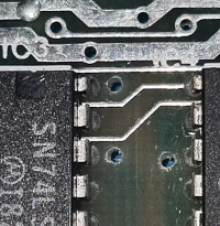
Where do you put the spider mod on an issue 2 after you've socketed the Z80? Answers by email. By ic4? I can understand not wanting to drill holes and doing everything component side. Not straight forward when there are sockets there.
 |
|
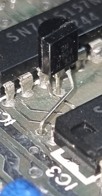
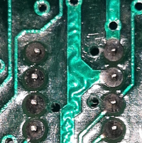
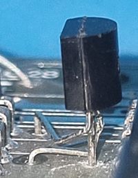
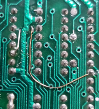
This is a 2n3904. Collector to ic3 pin 14 (5V). Base to ic4 pin 6 (A0). Emitter to ULA pin 33 (IOREQ).
Mod for compositeless (totally) RGBtoHDMI YUV changes - 1K for Y to ground - 1K9 to U to 5V (right of C68, C69 are good), 470R over R56 (U to 0) and 1K over R63.
Some luck has been had for parts from AliExpress for the ZX Spectrum. These links will probably stop working.
4116 RAM
74LS157
Keyboard Connectors
My RAM tester I used to test my ZX Spectrum RAM chips is here. Credits to Noel Llopis of Noel's Retro Lab and PCB Geeks.com for the board I've very slightly repurposed. Please see the header for more information.
To follow, just notes right now....
Started with an ATX PSU with an 7905 to take -12v to -5v to get things going. That was a bit big.
Latest version uses a buck converter and a 7805 (or substitute)7 with a standard 12V power brick, much simpler.
Using a standard monitor just takes inverting R, G, B and Vertical Sync. A 74LS04 is fine for this. I'll do something in paint whilst I work out KiCAD (?).